Product Description
Product Description
The gears in an Atlas air compressor play a critical role in the mechanical operation of the unit. Specifically, they are responsible for transferring rotational motion from the motor to the compressor’s main shaft or rotor assembly. This transfer of power enables the compressor to convert mechanical energy into compressed air, which is used for various industrial and commercial applications.
More specifically, the gears within the compressor help to achieve several key functions:
Power Transmission: Gears transmit power from the motor to the compressor’s main shaft or rotor assembly. This allows the compressor to convert the rotational motion of the motor into the reciprocating or rotary motion necessary for compressing air.
Speed Regulation: Depending on the design of the compressor, gears can also play a role in regulating the speed at which the compressor operates. By changing the gear ratio between the motor and the compressor’s moving parts, the compressor’s output can be adjusted to meet different air demand requirements.
Synchronization: In multi-stage compressors or compressors with multiple cylinders, gears ensure proper synchronization between various components. This synchronization is crucial for maintaining the efficiency and reliability of the compressor’s operation.
Load Distribution: Gears help distribute the load evenly across different components of the compressor, reducing wear and tear on individual parts and promoting longevity and reliability.
Overall, the gears in an Atlas air compressor are integral to its functionality, enabling efficient power transmission, speed regulation, synchronization, and load distribution within the compressor system.
AIRUNCO’s gears are made of typically high-strength alloy steel or cast iron.These materials offer excellent mechanical properties such as high strength, hardness, and wear resistance, suitable for withstanding the loads and pressures involved in compressor operation. Additionally, some gears may undergo surface treatments such as heat treatment or coating to enhance their wear resistance and corrosion resistance. The specific material selection depends on factors such as the design requirements of the compressor, load conditions, and expected service life.
| AC | GEAR | 1622311017 | |||||||||||||||||||
| AC | GEAR | 1622311018 | |||||||||||||||||||
| AC | GEAR | 1622311571 | |||||||||||||||||||
| AC | GEAR | 1622311026 | |||||||||||||||||||
| AC | GEAR | 1622311571 | |||||||||||||||||||
| AC | GEAR | 1622311571 | |||||||||||||||||||
| AC | GEAR | 1622311033 | |||||||||||||||||||
| AC | GEAR | 1622311034 | |||||||||||||||||||
| AC | GEAR | 1622311035 | |||||||||||||||||||
| AC | GEAR | 1622311036 | |||||||||||||||||||
| AC | GEAR | 1622311043 | |||||||||||||||||||
| AC | GEAR | 1622311044 | |||||||||||||||||||
| AC | GEAR | 1622311049 | |||||||||||||||||||
| AC | GEAR | 1622311050 | |||||||||||||||||||
| AC | GEAR | 1622311059 | |||||||||||||||||||
| AC | GEAR | 1622311060 | |||||||||||||||||||
| OEM | DESCRIPTION | OEM PART NO. | |||||||||||||||||||
| AC | GEAR | 1622311065 | |||||||||||||||||||
| AC | GEAR | 1622311066 | |||||||||||||||||||
| AC | GEAR | 1622311067 | |||||||||||||||||||
| AC | GEAR | 1622311068 | |||||||||||||||||||
| AC | GEAR | 1622311073 | |||||||||||||||||||
| AC | GEAR | 1622311074 | |||||||||||||||||||
| AC | GEAR | 1622 | |||||||||||||||||||
| AC | GEAR | 16138180W10/1615714W11 | |||||||||||||||||||
| AC | GEAR | 1622311056/1622311055 | |||||||||||||||||||
| AC | GEAR | 1622369242/1622369241 | |||||||||||||||||||
| AC | GEAR | 16149306 | |||||||||||||||||||
| AC | GEAR | 16231 0571 0-16231067z03 | |||||||||||||||||||
| AC | GEAR | 109257 | |||||||||||||||||||
| AC | GEAR | 109257 | |||||||||||||||||||
| AC | GEAR | 1622 | |||||||||||||||||||
| AC | GEAR | 16220571 | |||||||||||||||||||
| IR | GEAR | 92874502 | |||||||||||||||||||
| AC | GEAR | 16138443 | |||||||||||||||||||
| AC | GEAR | 1092571044 | |||||||||||||||||||
| AC | GEAR | 1622369253/1622369254 | |||||||||||||||||||
| AC | GEAR | 1614931/1614935710 | |||||||||||||||||||
| AC | GEAR | 1622571 (ESS) | 89243778 | ||||||||||||||||||
| IR | COMBICOOLER UP5 11/15KW | 22082499 | |||||||||||||||||||
| IR | COMBICOOLER UP5 22E/30KW | 22176986 | |||||||||||||||||||
| IR | COMBICOOLER UP5 37 KW | 22176978 | |||||||||||||||||||
| IR | COMBICOOLER IN 7.5/10/15KW | 99312944 | |||||||||||||||||||
| IR | COMBICOOLER UP5 18/22KW | 54753918 | |||||||||||||||||||
| IR | COMBICOOLER ML/MM/MH – 45/55 | 39893 | |||||||||||||||||||
| ELGI | THERMOSTATIC VALVE KIT | B0 0571 078 | |||||||||||||||||||
| ELGI | COMBICOOLER E18/E22 | 10345710 | |||||||||||||||||||
| ELGI | COMBICOOLER E18/E22 | B0 0571 069 | |||||||||||||||||||
| ELGI | COMBICOOLER E37 | 15711220 | |||||||||||||||||||
| ELGI | COMBICOOLER E37 | 103413 | |||||||||||||||||||
| ELGI | COMBICOOLER E45 | 10341250 | |||||||||||||||||||
| ELGI | COMBICOOLER E45 | B0 0571 069 | |||||||||||||||||||
| ELGI | COMBICOOLER E55 | 15712290 | |||||||||||||||||||
| ELGI | COMBICOOLER E75 | B777107 | |||||||||||||||||||
| ELGI | COMPRESSOR COOLER | B0 0571 069 | |||||||||||||||||||
| ELGI | COMPRESSOR COOLER | B0 0571 069 | |||||||||||||||||||
| ELGI | COMPRESSOR COOLER | B0 0571 069 | |||||||||||||||||||
| ELGI | COMPRESSOR COOLER | B0 0571 069 | |||||||||||||||||||
| ELGI | COMPRESSOR COOLER | B777109 | |||||||||||||||||||
| ELGI | COMPRESSOR COOLER | B777108 | |||||||||||||||||||
| ELGI | COMPRESSOR COOLER | B777110 | |||||||||||||||||||
| ELGI | COMPRESSOR COOLER | B777109 | |||||||||||||||||||
| ELGI | COMPRESSOR COOLER | B777108 | |||||||||||||||||||
| ELGI | COMPRESSOR COOLER | B0 0571 0690014 | |||||||||||||||||||
| KS | COUPLING WITH HEX SCREWS | 5.3177E.0571 | |||||||||||||||||||
| KS | COUPLING WITH HEX SCREWS | 5.3129.0 | |||||||||||||||||||
| KS | COUPLING WITH HEX SCREWS | 5.3129.E3 | |||||||||||||||||||
| KS | COUPLING WITH HEX SCREWS | 5.3246.0 | |||||||||||||||||||
| KS | COUPLING WITH HEX SCREWS | 5.3130.0 | |||||||||||||||||||
| KS | COUPLING WITH HEX SCREWS | 5.3131.0 | |||||||||||||||||||
| KS | COUPLING WITH HEX SCREWS | 5.3132.0 | |||||||||||||||||||
| KS | PNEUMATIC OPER VALVE MAINT KIT | 401972 | |||||||||||||||||||
| KS | CAVV KIT | 400706 | |||||||||||||||||||
| KS | CAVV KIT | 400905 | |||||||||||||||||||
| KS | CAVV KIT | 400707.0002 | |||||||||||||||||||
| KS | CAVV KIT | 400707 | |||||||||||||||||||
| KS | MPCV KIT | 40571.1 | |||||||||||||||||||
| KS | MPCV KIT | 400982.1/2 | |||||||||||||||||||
| KS | MPCV KIT | 457113 | |||||||||||||||||||
| OEM | DESCRIPTION | OEM PART NO. | |||||||||||||||||||
| KS | MPCV KIT | 400983.3 | |||||||||||||||||||
| KS | MPCV KIT | 4571.1 | |||||||||||||||||||
| KS | COMBINATION VALVE KIT | 4571.0003 | |||||||||||||||||||
| KS | COMBINATION VALVE KIT | 40 0571 .0001 | |||||||||||||||||||
| KS | COMBINATION VALVE KIT | 40 0571 .0002 | |||||||||||||||||||
| KS | CONTROL LINE KIT | 400904 | |||||||||||||||||||
| KS | CONTROL LINE KIT | 4 7 | |||||||||||||||||||
| KS | CONTROL LINE KIT | 40571 | |||||||||||||||||||
| KS | INTAKE KIT | 40571 | |||||||||||||||||||
| KS | INTAKE KIT | 40571 | |||||||||||||||||||
| KS | INTAKE KIT | 4 1 | |||||||||||||||||||
| KS | INTAKE KIT | 40571 | |||||||||||||||||||
| KS | INTAKE KIT | 40571 | |||||||||||||||||||
| KS | INTAKE KIT | 401809 | |||||||||||||||||||
| KS | ECO DRAIN WEAR KIT 12 | 8.2449.0 | |||||||||||||||||||
| KS | ECO DRAIN WEAR KIT 13 | 8.2454.0 | |||||||||||||||||||
| KS | ECO DRAIN WEAR KIT 14 | 8.2519.0 | |||||||||||||||||||
| KS | FILTER MAT 110MM | 6.3572.0 | |||||||||||||||||||
| KS | KAESER COMPRESSOR COOLER | 5.7605.2 | |||||||||||||||||||
| KS | KAESER COMPRESSOR COOLER | 5.3678.0 | |||||||||||||||||||
| KS | KAESER COMPRESSOR COOLER | 5.7601E1 | |||||||||||||||||||
| KS | KAESER COMPRESSOR COOLER | 5.7602.1 | |||||||||||||||||||
| KS | KAESER COMPRESSOR COOLER | 5.3677 | |||||||||||||||||||
| KS | KAESER COMPRESSOR COOLER | 1109.571.2210D / 1109.031.0000 | |||||||||||||||||||
| KS | KAESER COMPRESSOR COOLER | 4571571 | |||||||||||||||||||
| KS | KAESER COMPRESSOR COOLER | 5.7608.1 | |||||||||||||||||||
| KS | KAESER COMPRESSOR COOLER | 5.7603EO 5.7603.0 | |||||||||||||||||||
| AC | PRESSURE TRANSDUCER | 1 0571 7128 | |||||||||||||||||||
| AC | PRESSURE TRANSDUCER | 1 0571 7178 | |||||||||||||||||||
| AC | PRESSURE TRANSDUCER | 1 0571 7151 | |||||||||||||||||||
| AC | PRESSURE TRANSDUCER | 1 0571 7141 | |||||||||||||||||||
| AC | PRESSURE TRANSDUCER | 1 0571 7173 | |||||||||||||||||||
| AC | PRESSURE TRANSDUCER | 1 0571 7133 | |||||||||||||||||||
| AC | PRESSURE TRANSDUCER | 1 0571 7165 | |||||||||||||||||||
| AC | PRESSURE TRANSDUCER | 1 0571 7174 | |||||||||||||||||||
| AC | PRESSURE TRANSDUCER | 1 0571 7144 | |||||||||||||||||||
| AC | PRESSURE TRANSDUCER | 1 0571 7154 | |||||||||||||||||||
| AC | PRESSURE TRANSDUCER | 1 0571 7137 | |||||||||||||||||||
| AC | PRESSURE TRANSDUCER | 1 0571 7126 | |||||||||||||||||||
| AC | DIFF PRESSURE TRANSDUCER | 1 0571 7120 | |||||||||||||||||||
| AC | DIFF PRESSURE TRANSDUCER | 1 0571 7143 | |||||||||||||||||||
| AC | DIFF PRESSURE TRANSDUCER | 1089962501 | |||||||||||||||||||
| AC | DIFF PRESSURE TRANSDUCER | 1089962502 | |||||||||||||||||||
| AC | TEMPERATURE SENSOR | 1 0571 7107 | |||||||||||||||||||
| AC | TEMPERATURE SENSOR | 1 0571 7149 | |||||||||||||||||||
| AC | TEMPERATURE SENSOR | 1 0571 7170 | |||||||||||||||||||
| AC | TEMPERATURE SENSOR | 1 0571 7104 | |||||||||||||||||||
| AC | TEMPERATURE SENSOR | 1 0571 7155 | |||||||||||||||||||
| AC | TEMPERATURE SENSOR AMBIENT | 1 0571 7112 | |||||||||||||||||||
| OEM | DESCRIPTION | OEM PART NO. | |||||||||||||||||||
| AC | PRESSURE SENSOR | 1089962512 | |||||||||||||||||||
| AC | PRESSURE SENSOR | 1089962516 | |||||||||||||||||||
| AC | PRESSURE SENSOR | 1089962518 | |||||||||||||||||||
| AC | PRESSURE SENSOR | 1089962532 | |||||||||||||||||||
| AC | PRESSURE SENSOR | 1089962533 | |||||||||||||||||||
| AC | PRESSURE SENSOR | 1089962513 | |||||||||||||||||||
| AC | PRESSURE SENSOR | 1089962534 | |||||||||||||||||||
| AC | PRESSURE SENSOR | 1089962535 | |||||||||||||||||||
| AC | PRESSURE SENSOR | 1089962536 | |||||||||||||||||||
| AC | PRESSURE SENSOR | 1089962537 | |||||||||||||||||||
| AC | TEMPERATURE SWITCH | 157163709 | |||||||||||||||||||
| AC | TEMPERATURE SWITCH | 157163716 | |||||||||||||||||||
| AC | TEMPERATURE SWITCH | 157163713 | |||||||||||||||||||
| CP | PRESSURE SENSOR | 22571103 | |||||||||||||||||||
| CP | TEMPERATURE SENSOR | 22571104 | |||||||||||||||||||
| CP | PRESSURE SENSOR | ||||||||||||||||||||
| CP | PRESSURE SENSOR | ||||||||||||||||||||
| ELGI | TEMPERATURE SENSOR ELGI COMMON | 0 0571 902C | |||||||||||||||||||
| ELGI | WIRE FOR TEMP SENSOR ELGI | 0 0571 902C-W | |||||||||||||||||||
| ELGI | PRESSURE SENSOR ELGI COMMON | 0 0571 901C | |||||||||||||||||||
| IR | TEMPERATURE SENSOR IR ML 55 – 75 | 37952439 | |||||||||||||||||||
| IR | TEMPERATURE SENSOR IR ML 55 – 75 | 39586227 | |||||||||||||||||||
| IR | TEMPERATURE SENSOR IR ML 90 – 160 | 37952355 | |||||||||||||||||||
| IR | TEMPERATURE SENSOR IR | 39560628 | |||||||||||||||||||
| IR | TEMPERATURE SENSOR (NEW) | 22137848 | |||||||||||||||||||
| IR | PRESSURE SENSOR IR COMMON | 39853809 | |||||||||||||||||||
| IR | PRESSURE SENSOR IR NEW | 22359632 | |||||||||||||||||||
| IR | PRESSURE SENSOR IR NEW | 39875539 | |||||||||||||||||||
| IR | PRESSURE SENSOR IR NEW | 39877618 | |||||||||||||||||||
| IR | TEMPERATURE SWITCH IR ML 55-160 | 37952264 | |||||||||||||||||||
| IR | TEMPERATURE SWITCH IR UP 5 SERIES | 37952421 | |||||||||||||||||||
| IR | TEMPERATURE SWITCH IR LASE / XF | 39419668 | |||||||||||||||||||
| IR | TEMPERATURE SWITCH IR | 39416128 | |||||||||||||||||||
FAQ
Q1: What is the minimum order quantity (MOQ) for your air compressor parts?
Answer: Our minimum order quantity varies depending on the specific part. The majority of accessories can be ordered with a minimum quantity of one.Please refer to our product catalog or contact our sales team for detailed information on MOQ.
Q2: Do you offer sample shipments for evaluation before placing a bulk order?
Answer: Yes, we do offer sample shipments to allow customers to evaluate the quality and compatibility of our air compressor parts. This requires customers to cover the cost of both the sample and shipping fees. Please contact our sales team to inquire about sample availability and shipping details.
Q3: What types of air compressor parts are commonly available for replacement?
Answer: Our inventory includes a wide range of air compressor parts such as filters, valves, pistons, gaskets, compressor oil, and more to meet diverse replacement needs.
Q4: How often should I replace the air filters in my compressor system?
Answer: It is recommended to replace air filters regularly, typically every 3 to 6 months, to maintain optimal air quality and ensure efficient compressor performance.
Q5: Are your air compressor parts compatible with different compressor brands and models?
Answer: Yes, our air compressor parts are designed for compatibility with various brands and models, offering flexibility in replacement options.
Q6: What are the key benefits of using OEM (Original Equipment Manufacturer) air compressor parts?
Answer: OEM parts ensure the highest quality, precision fit, and adherence to manufacturer specifications, resulting in improved performance, longevity, and warranty protection.
Q7: How can I identify the right air compressor part for my specific model?
Answer: Our website provides detailed product information, and our salesman and technician support team are available to assist you in identifying the correct part for your air compressor model.
Q8: What maintenance tips do you recommend for prolonging the life of air compressor parts?
Answer: Regular inspection, timely replacement of consumables, and adherence to manufacturer-recommended maintenance schedules are essential for maximizing the lifespan and efficiency of air compressor parts.
/* January 22, 2571 19:08:37 */!function(){function s(e,r){var a,o={};try{e&&e.split(“,”).forEach(function(e,t){e&&(a=e.match(/(.*?):(.*)$/))&&1
| Application: | Machinery |
|---|---|
| Hardness: | Hardened Tooth Surface |
| Manufacturing Method: | Cast Gear |
| Samples: |
US$ 450/Set
1 Set(Min.Order) | Order Sample |
|---|
| Customization: |
Available
| Customized Request |
|---|
.shipping-cost-tm .tm-status-off{background: none;padding:0;color: #1470cc}
|
Shipping Cost:
Estimated freight per unit. |
about shipping cost and estimated delivery time. |
|---|
| Payment Method: |
|
|---|---|
|
Initial Payment Full Payment |
| Currency: | US$ |
|---|
| Return&refunds: | You can apply for a refund up to 30 days after receipt of the products. |
|---|
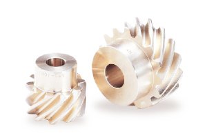
How does a screw gear impact the overall efficiency of a system?
A screw gear, also known as a worm gear, plays a significant role in the overall efficiency of a system. The design and characteristics of the screw gear can influence several factors that affect the system’s efficiency. Here’s a detailed explanation of how a screw gear impacts the overall efficiency of a system:
- Gear Ratio: The gear ratio of a screw gear system determines the relationship between the input and output speeds. In a screw gear, the gear ratio is typically high, which means that a small rotation of the worm gear results in a larger rotation of the worm wheel. This high gear ratio allows for precise control and slow movement, but it also leads to a trade-off in terms of mechanical efficiency. The high gear ratio can result in a lower mechanical efficiency due to increased friction and power loss.
- Friction and Efficiency: Screw gears inherently introduce more friction compared to other gear types due to the sliding motion between the worm and the worm wheel. This sliding action generates friction, which can reduce the overall efficiency of the system. The efficiency of a screw gear system depends on various factors, including the materials used, the lubrication, and the design parameters. Proper lubrication and the use of high-quality materials can help minimize friction and improve the efficiency of the system.
- Lubrication and Efficiency: Adequate lubrication is crucial for reducing friction and maximizing the efficiency of a screw gear system. The lubricant forms a film between the contacting surfaces of the worm gear and worm wheel, reducing direct metal-to-metal contact and minimizing frictional losses. Insufficient or improper lubrication can lead to increased friction, higher operating temperatures, and reduced efficiency. Therefore, proper lubrication, including the selection of the appropriate lubricant type and viscosity, is essential for optimizing the efficiency of the system.
- Backlash: Backlash refers to the play or clearance between the mating teeth of the worm gear and worm wheel. Excessive backlash can lead to energy loss and reduced efficiency. It can cause vibrations, impacts, and inefficient power transmission. Therefore, minimizing backlash through precise manufacturing and proper meshing of the gears is essential for maintaining high efficiency in a screw gear system.
- Mechanical Efficiency: The mechanical efficiency of a screw gear system is influenced by various factors, including the design, manufacturing tolerances, lubrication, load conditions, and operating speed. In general, screw gears tend to have lower mechanical efficiency compared to other gear types, such as spur gears or helical gears. However, advancements in gear design, materials, and lubrication technologies have improved the overall efficiency of screw gear systems in recent years.
- Application Considerations: The impact of a screw gear on the overall efficiency of a system also depends on the specific application requirements. Screw gears are commonly used in applications that prioritize precise motion control over high efficiency, such as in applications requiring heavy loads or precise positioning. In such cases, the advantages of screw gears, such as high gear ratios and self-locking capabilities, outweigh the potential efficiency trade-offs.
It is important to note that the overall efficiency of a system is influenced by multiple factors beyond the screw gear itself, including other components, power transmission losses, and system design. Therefore, when evaluating the efficiency of a system, it is essential to consider the collective impact of all components and factors involved.
How do you address thermal expansion and contraction in a screw gear system?
Addressing thermal expansion and contraction in a screw gear system is crucial to ensure the proper functioning and longevity of the system. Thermal expansion and contraction occur when a system is subjected to temperature changes, leading to dimensional changes in the components. Here’s a detailed explanation of how to address thermal expansion and contraction in a screw gear system:
- Material Selection: Choose materials for the screw gear system components that have compatible coefficients of thermal expansion (CTE). Using materials with similar CTE can help minimize the differential expansion and contraction between the components, reducing the potential for misalignment or excessive stress. Consider materials such as steel, bronze, or other alloys that exhibit good dimensional stability over the expected operating temperature range.
- Design for Clearance: Incorporate proper clearances and tolerances in the design of the screw gear system to accommodate thermal expansion and contraction. Allow for sufficient clearance between mating components to accommodate the expected dimensional changes due to temperature variations. This can prevent binding, excessive friction, or damage to the gears during temperature fluctuations.
- Lubrication: Utilize appropriate lubrication in the screw gear system to mitigate the effects of thermal expansion and contraction. Lubricants can help reduce friction, dissipate heat, and provide a protective film between the mating surfaces. Select lubricants that offer good thermal stability and maintain their properties across the expected temperature range of the system.
- Thermal Insulation: Implement thermal insulation measures to minimize the exposure of the screw gear system to rapid temperature changes. Insulating the system from external heat sources or environmental temperature fluctuations can help reduce the thermal stresses and minimize the effects of expansion and contraction. Consider using insulating materials or enclosures to create a more stable temperature environment around the screw gear system.
- Temperature Compensation Mechanisms: In certain applications, it may be necessary to incorporate temperature compensation mechanisms into the screw gear system. These mechanisms can actively or passively adjust the position or clearance between components to compensate for thermal expansion or contraction. Examples include thermal expansion compensation screws, bimetallic elements, or other devices that can accommodate dimensional changes and maintain proper alignment under varying temperatures.
- Operational Considerations: Take into account the thermal characteristics of the environment and the operational conditions when using a screw gear system. If the system is expected to experience significant temperature variations, ensure that the operating parameters, such as load capacities and operating speeds, are within the design limits of the system under the anticipated temperature range. Monitor and control the temperature of the system if necessary to minimize the effects of thermal expansion and contraction.
- System Testing and Analysis: Conduct thorough testing and analysis of the screw gear system under various temperature conditions to assess its performance and behavior. This can involve measuring dimensional changes, analyzing gear meshing characteristics, and evaluating the system’s ability to maintain proper alignment and functionality. Use the test results to validate the design, make any necessary adjustments, and optimize the system’s performance under thermal expansion and contraction effects.
- Maintenance and Inspection: Establish a regular maintenance and inspection routine for the screw gear system to monitor its performance and address any issues related to thermal expansion and contraction. This can involve checking clearances, lubrication levels, and the overall condition of the system. Promptly address any signs of excessive wear, misalignment, or abnormal operation that may be attributed to temperature-related effects.
By considering material selection, design clearances, lubrication, thermal insulation, temperature compensation mechanisms, operational considerations, and regular maintenance, it is possible to effectively address thermal expansion and contraction in a screw gear system. These measures help ensure the system’s reliability, minimize wear and damage, and maintain the desired performance and functionality over a range of operating temperatures.
Are there different types of screw gears available?
Yes, there are different types of screw gears available, each with its variations in design and functionality. These variations cater to specific applications and requirements. Here are some of the commonly used types of screw gears:
- Single-Thread Worm Gears: Single-thread worm gears have a single helical thread on the worm. They provide a relatively higher gear ratio and are commonly used in applications requiring moderate torque and precision positioning. Single-thread worm gears are widely employed in industries such as manufacturing, automotive, and machinery.
- Multi-Thread Worm Gears: Multi-thread worm gears have multiple helical threads on the worm, typically two or more. The presence of multiple threads increases the contact area and allows for higher torque transmission. Multi-thread worm gears offer higher gear reduction ratios and are suitable for applications requiring greater torque multiplication, such as heavy-duty machinery and high-load lifting systems.
- Fine-Pitch Worm Gears: Fine-pitch worm gears have a smaller pitch, meaning there are more teeth per unit length of the worm. This design allows for finer control and precise positioning. Fine-pitch worm gears find applications in industries where accurate motion control is critical, such as robotics, automation, and optics.
- Coarse-Pitch Worm Gears: Coarse-pitch worm gears have a larger pitch, resulting in fewer teeth per unit length of the worm. This design provides higher torque transmission and is suitable for applications requiring heavy-duty power transmission. Coarse-pitch worm gears are commonly used in industries like manufacturing, material handling, and conveyors.
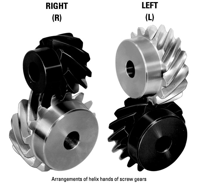
- Right-Handed and Left-Handed Worm Gears: Screw gears can be classified as right-handed or left-handed based on the direction of the helical thread. In a right-handed worm gear, the helical thread advances in a clockwise direction when viewed from the end of the worm. In a left-handed worm gear, the helical thread advances counterclockwise. The choice between right-handed and left-handed worm gears depends on the specific application and the desired rotational direction.
- Non-Throated and Throated Worm Gears: Non-throated worm gears have a cylindrical worm without a groove, while throated worm gears have a groove or a notch on the worm. The presence of a throat allows for greater contact between the worm and the worm wheel, increasing the gear meshing efficiency and load-carrying capacity. Throated worm gears are commonly used in applications where higher efficiency and load capacity are required.
- Self-Locking Worm Gears: Self-locking worm gears are designed to have a high self-locking capability. The helical thread angle and the friction between the worm and the worm wheel prevent the worm wheel from backdriving the worm when the system is at rest. Self-locking worm gears are widely used in applications that require holding a position without the need for additional braking or locking mechanisms, such as elevators, lifts, and positioning systems.
These are some of the different types of screw gears available in the market. The selection of a specific type depends on factors such as torque requirements, gear reduction ratio, precision positioning, load capacity, and self-locking capabilities, among others. Understanding the characteristics and variations of screw gears allows for choosing the most suitable type for a given application.


editor by Dream 2024-05-06